Terrain rendering can be done in many ways depending on the scope, scale, and desired visual quality. My ultimate goal is to render an entire planet, with rich detail from any viewpoint and the ability to zoom in/out and see the curvature of the planet. But as a first step, let’s just render a “normal” terrain, using a height-map and simple polygon reduction.
Height-map definition
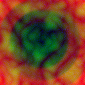
A height-map is simply an image with elevation information. The basic form is a grey-scale image where the luminance at each pixel represents elevation. But this can give only 8 bit precision and is not enough to represent a highly detailed terrain (in a grey-scale image, all color components have the same 8-bit value). A more popular way is to use all 4 channels of the image to reach 32-bit precision. But I determined 24-bit is enough for the kind of detail I want so I went for a height-map with 3 channels worth of information: Basically, each channel is responsible for a different spacial magnitude, and when combining all three I get a very smooth terrain.
In my case, Red can displace in units of 100 (low frequency displacement), Green in units of 20 (medium frequency), and Blue in units of 5 (high frequency) – those are arbitrary values, completely tweak-able. For example, the following height-map, composed of the following channels, produces the terrain below:


Polygon complexity
The above 512×512 height-map has 262144 pixels and produces a mesh with as many vertices. This can easily amount to 250K triangles. For a 1024×1024 height-map, you can easily reach 1M triangles. At this point polygon reduction seems like a must to keep the terrain complexity under control.
The best practice is to do this reduction at run-time, where pieces of the terrain dynamically change resolution depending on the distance from the viewer. The part of the terrain that is closest needs to have the highest definition, and the farthest need not. Generally speaking, adapting mesh complexity to the view distance (or to any factor, it can be the screen-space area) is called Level of Detail (LOD) determination.
Currently, I don’t need to do real-time LOD. For the kind of game I’m making, statically reducing the terrain complexity, combined with dynamic visibility determination using a Quadtree and Frustum culling, gives good results.
Polygon reduction using a Quadtree
A Quadtree is ideal for representing spatial information. In the case of terrain simplification, it can be used to “approximate” the terrain, and then we can create a mesh based on its structure.
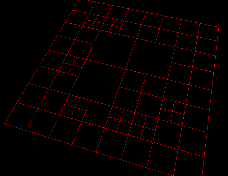
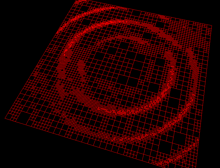
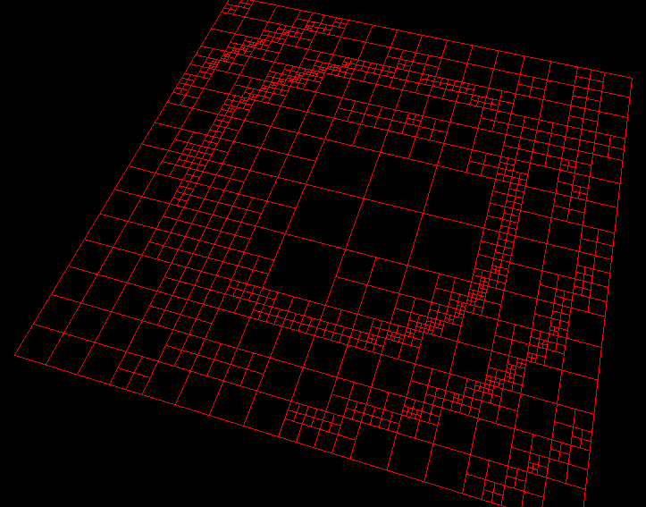
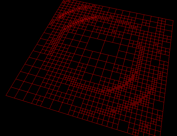
In order to build the Quadtree, we must have a criteria to decide if we should sub-divide a node or not. In my case, I chose the criteria to be the “height variation” of the vertices within a node. If all the vertices are approximately at the same height (within a certain threshold), I assume they can be “approximated” as a single flat patch, otherwise, I keep subdividing until the height variation is low enough.
The following is an example of how a terrain is approximated using a Quadtree, with different height variation thresholds:
Terrain tesselation using a Quadtree
Now that we have our Quadtree representation, we must create a mesh. As a first step, let’s assume all the vertices have zero height to keep it simple, build our mesh, and then apply elevation as a last step.
Now it seems like all we have to do is add vertices at the corners of the quadtree nodes, and connect them to have a terrain right? Not so simple dude. The main challenge is to be able to address the vertices in a predictable way, to be able to build triangles out of them. Basically before you can make a triangle out of vertices x, y, z, you need to know that x, y, z are a valid combination. A good way to do this is to only allow adding vertices to pre-determined locations on the quadtree nodes. For example, here are 9 valid positions for a vertex on a node:
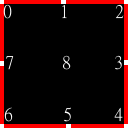
This makes triangulation trivial, we know which triangles to create based on the vertices.
Preparing the Quadtree
The problem now is that it’s not always possible to have these nice, predictable vertex positions on certain nodes, specially between nodes that have a very different subdivision level. When two neighboring nodes have a subdivision difference greater than 1, the 9 positions are not enough, you need to add more vertices to correctly represent the structure. Things just got out of hand again, by not being able to pre-determine the vertex positions you can’t determine the triangles easily. The following picture illustrates the problem:
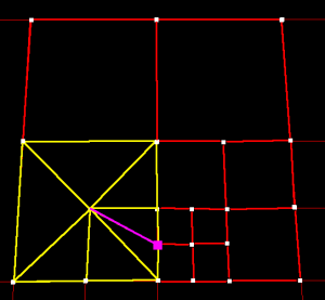
The good thing is that we don’t have to solve this problem, it’s simpler to create a situation where it doesn’t exist: Basically, by making sure two neighboring nodes can’t have a subdivision difference greater than 1, those nice 9 vertex spots will always be enough to translate the quadtree into a terrain.
So let’s iterate through it and determine the neighbors for each node. If a node has more than 2 neighbors on any side, we subdivide it. We repeat this process many times until no node needs subdivision. And tada, this yields the following quadtree (on the right) where two neighboring nodes can’t have a subdivision difference great than 1. On the left is the old quadtree.
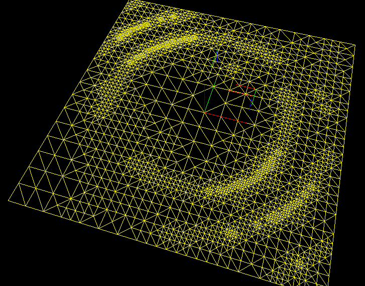
Building the mesh
Now we have a tesselation-friendly quadtree, where each node can reference at most 9 vertices. We can start adding the vertices to the terrain. Of course, we only add a vertices to leaf nodes, and make sure there are no duplicates. If a vertex is shared between 2 nodes, they both simply point to the same vertex instance. The unique vertex instances are accumulated in the terrain and will later end up in a VertexBuffer. After all vertices have been added, it’s time to build an IndexBuffer to contain triangle information. It’s easy to add triangles based on the vertex locations in each node. Basically, if a node has only corner vertices, we make 2 triangles out of it. Otherwise, if it has at least one edge vertex, we add a center vertex and create triangles based on the presence of each edge vertex. Here is how the terrain looks at this point:
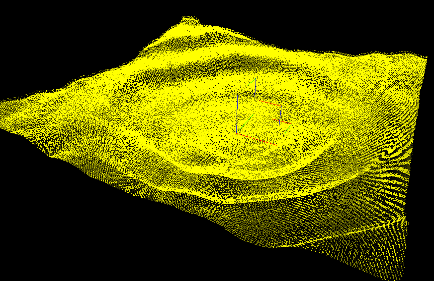
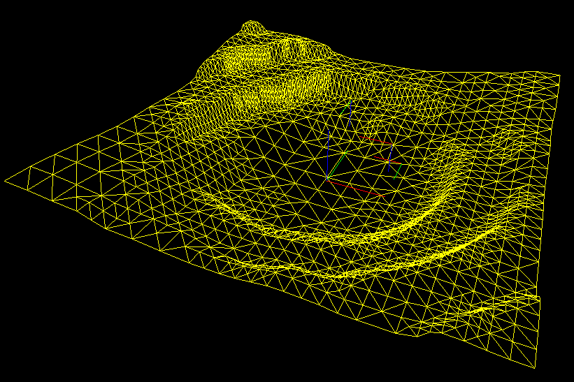
Elevating the vertices
The last step is to elevate the vertices based on the height-map data. The important thing is to keep track of the parent nodes for each vertex. This can be done at the tessellation stage. Then, we sample the pixels corresponding to each leaf node, and determine an average height for that node. Finally, for each vertex, we iterate through the parent nodes and determine a final average height. For a better approximation, the latter average should be weighted, meaning the parent nodes that cover more height-map pixels should have a higher impact on the average. This is how the terrain looks after elevation:
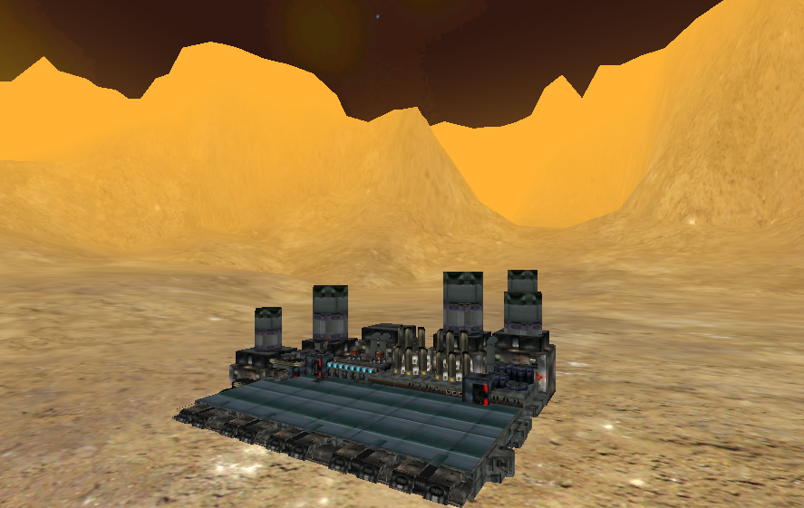
Final result
After texturing the terrain and adding some fog, here is how my in-game environment looks now: